Cirrus 1 is finished. One year, one month and eighteen days after the first bench test, the cloud chamber is fully assembled, enclosed and running under its own control system. Performance testing is still under way, but the build is done, and I am pretty happy about that.
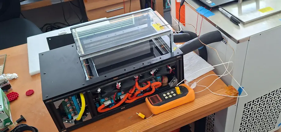
This post is a look back at how it came together. The detailed build logs for each subsystem are still to come.
Where it started
Towards the end of 2022, I put together this very simple working example of a Langsdorf Diffusion Cloud Chamber that you can see operating in this video.
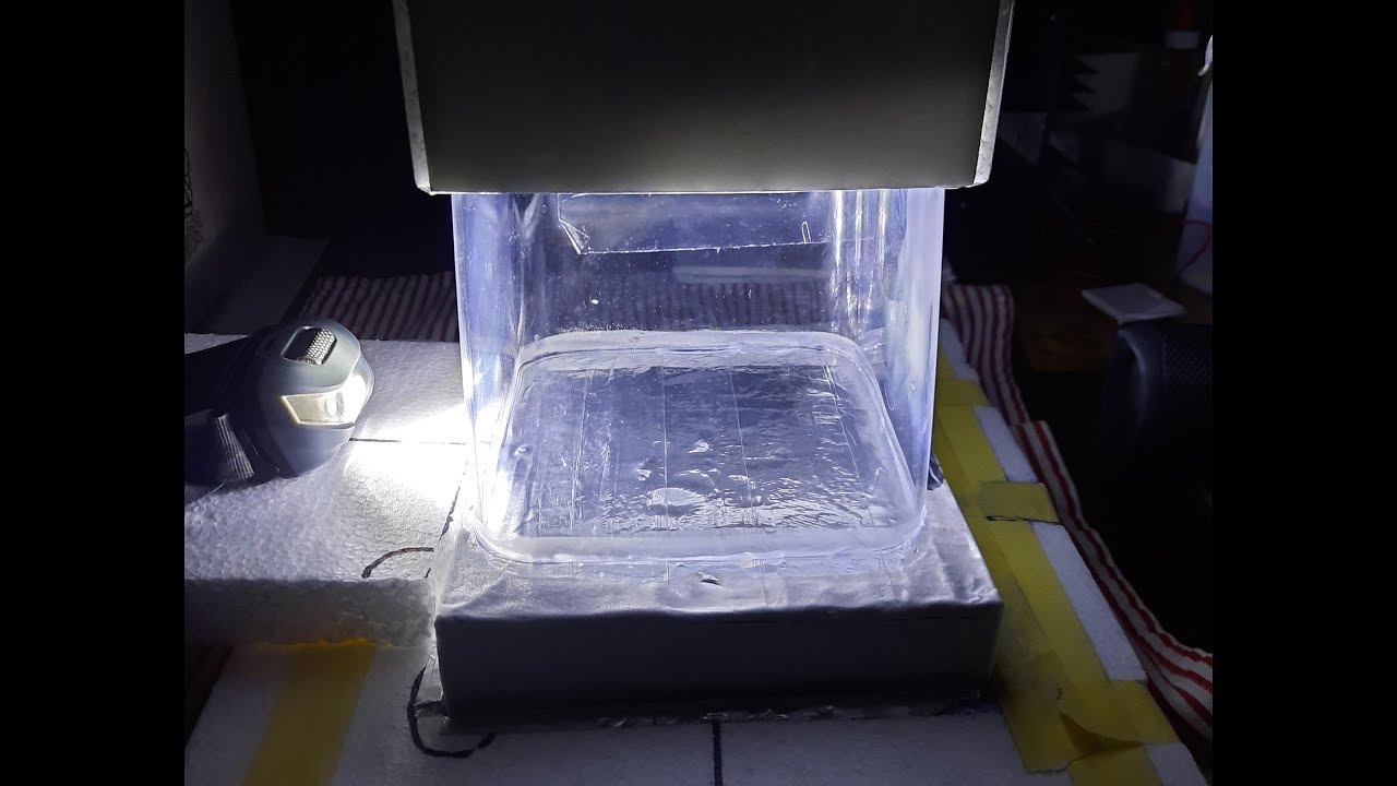
Once I saw the first tracks, and how easy it was to put together, I set about turning it up to 11 and making a machine that was not easy to put together 🙂
Initial testing was the usual experimentation with Peltier TECs, a bench supply, and a cheap thermometer, just to see how cold it could actually get. The answer was encouraging enough to keep going.. onward down the rabit hole.
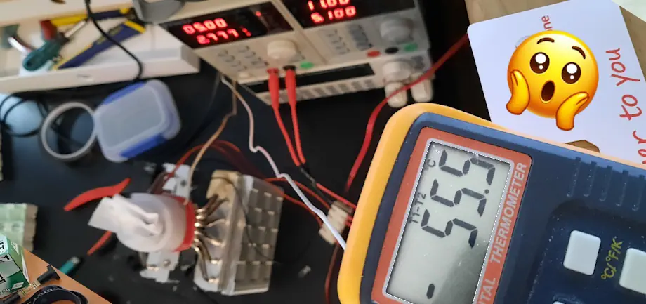
From there, the project split into two halves: the cold side (the cooling assembly and the glass chamber, both covered in earlier posts) and the electronics needed to drive it all.
The control system
Rather than one big board, Cirrus 1 is run by a set of small, reusable boards. A ZT-PICO2 controller, built around a Raspberry Pi Pico 2 W, sits in the middle, and each job gets its own module plugged into it over a ZapLink port. The first revisions started arriving in late 2025.
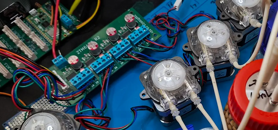
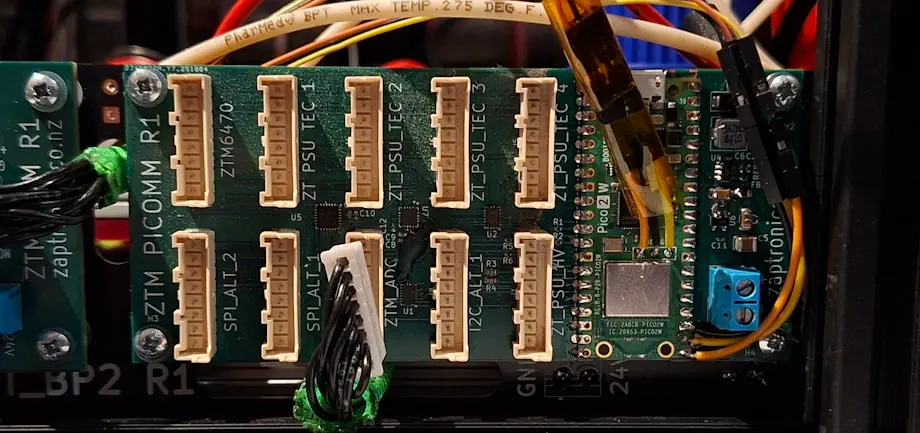
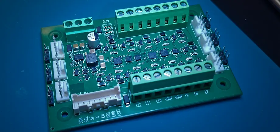
Every board that went into Cirrus 1 is now in the shop with a register-interest form:
- ZT-PICO2 Controller: runs everything.
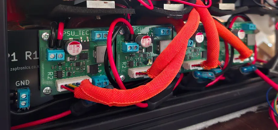
- ZTM-PSU-TEC Peltier (TEC) Driver: four of them, two TECs each, driving the eight Peltier modules under the cold plate.
- ZTM-ADC Temperature Probe Interface: reads the Pt1000 RTDs bonded to the cold plate and the other temperature probes.
- ZTM-PSU-HV HV Field Supply: powers the ion-sweeping field between the ITO top glass and the grounded plate.
- ZTM-6470 Quad Stepper Driver: runs the peristaltic pumps for the IPA loop.
- ZTM-PWM Load & Fan Driver: fans, LED lighting, the glass heater and the other loads.
The pumps had their own round of testing early on.

Later revision boards were much more reliable.
The chiller arrives
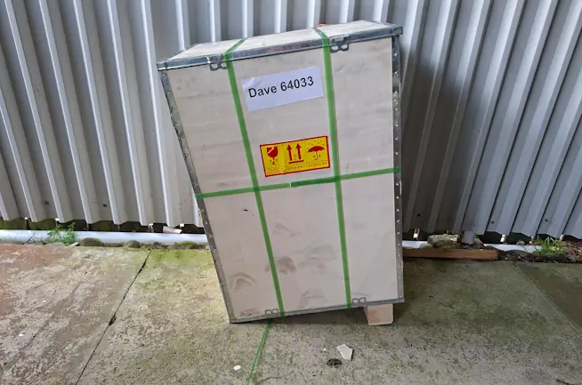
The hot side of the Peltier stack has to dump its heat somewhere. That job went to a recirculating glycol chiller, which arrived in July in a wooden crate and has been holding the coolant at about −20 °C ever since.

Putting it all together
Most of July to September went into wiring. Every board, pump, and power supply was positioned into the aluminium frame under the cold plate, with the TEC leads in orange braided sleeving, chosen on the well-established principle that orange looks fast.
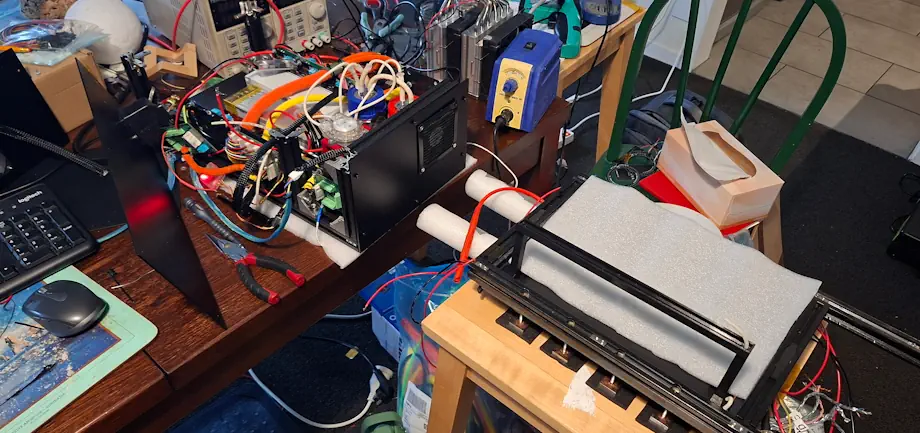
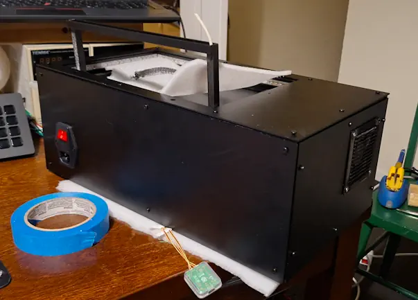
By early October the panels were on and it finally looked like an instrument instead of an explosion in a cable factory.
First full run
On 10 October the whole system ran together for the first time: chiller, TECs, pumps, fans and lighting, all driven from the ZT-PICO2 and watched over a network console on a laptop. Every module reported in.
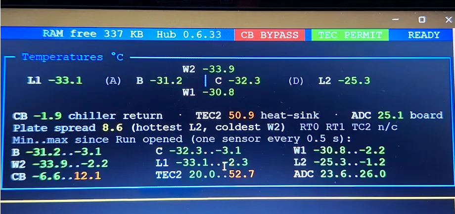
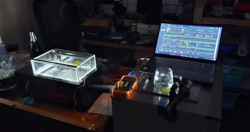
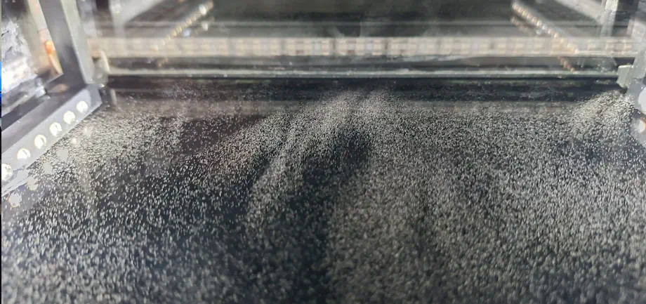
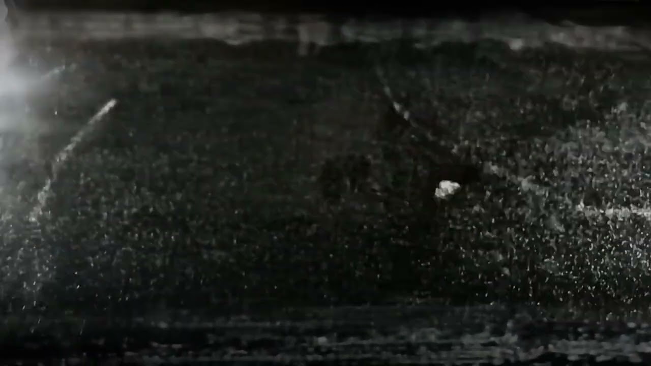
Within about twenty minutes the cold plate was down to around −32 to −33 °C, inside the −30 to −40 °C design target, and the supersaturated layer formed over the plate. Supersaturated vapour wants to condense and is just waiting for an excuse. A passing charged particle is an excellent excuse.
What is next
The build is complete, but the tuning is not. On the first run there was about an 8 °C spread across the plate between the warmest and coldest sensors, and evening that out, along with tuning the temperature gradient and the clearing field for the best track visibility, is what the performance testing is about. Results, and hopefully some good track videos, will follow.
In the meantime, the detailed build logs for each board are next on the list. If you want to build something similar, the product pages above are the place to register interest.
READER FEEDBACK
Join the discussion
Questions, build notes, corrections, and experimental observations are welcome.