The glass enclosure sits on top of the cold plate, shielding the internal environment from external perturbations and creating the required vertical temperature gradient. The aim is not to create an airtight container; the pressure needs to be equalised. It’s more important to prevent drafts from moving the IPA vapour about.
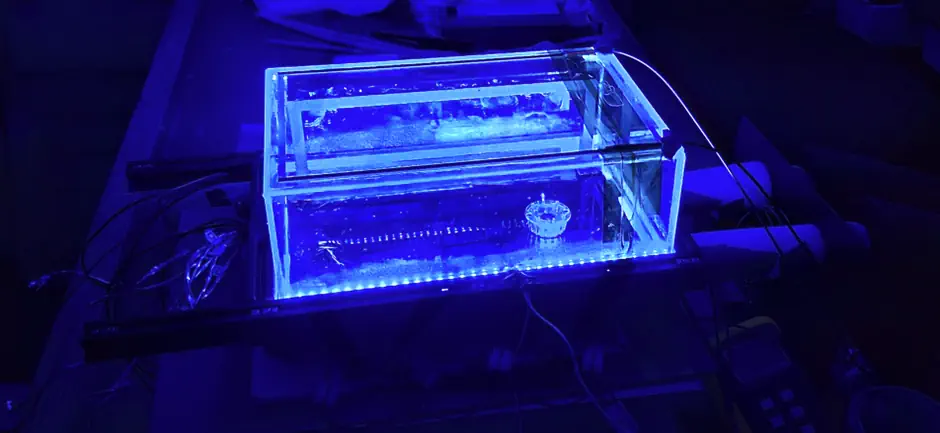
The temperature gradient is created by holding the glass temperature at around 25°C , while the bottom cold plate at -30°C to -40°C. At least that was the design target. The gradient is later tuned for best track visibility, and so must be controllable.
The overall chamber size is 290x190x100mm.
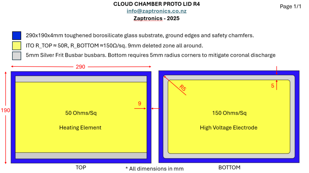
As the top sheet of glass is our primary viewing window, we want it to be as clear as possible, but it simultaneously needs to perform two independent functions. First, it needs to be kept at a constant temperature, and second, it needs to support a high-voltage electrode for ion sweeping.
Both problems are solved by using our double-sided ITO-coated glass panels. The drawing below is mostly self-explanatory.
Other cloud chamber builds use hot air heating of the glass from the outside, and a series of thin wires suspended just below the glass inside to create a high-voltage field.
We use transparent conductive ITO coatings to heat the glass on one side and create the high voltage electrode on the other; both are fully electrically isolated from one another.
The inner ITO coating forms a full-area transparent high-voltage anode, producing a broadly uniform electrostatic ion-sweeping field between the top glass and grounded cold plate. Field uniformity is the key advantage of a full surface electrode, and the bonus is no visible wires crossing the viewing path.
ITO Removal
Turns out double-sided ITO has a manufacturing step that makes it difficult to ensure the 9mm deleted zone around the edge of the glass is completely free of the conductive coating. It’s critical to ensure that this is a glass-only zone to meet the clearance requirement between the high-voltage side and the exterior of the chamber, where fingers are going to find themselves.
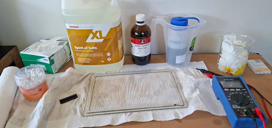
Luckily, a simple and effective ITO etchant can be made from ferric chloride and hydrochloric acid, both readily available from a local electronics store and hardware store, respectively.
The ferric chloride concentration was 40%, while the “spirit of salts” was around 24%. Some quick AI chemistry arrived at a 1.8:1 ratio of the aqueous HCl to FeCl₃.
⚠️Please use appropriate PPE and ventilation if you attempt this yourself.
This corrosive concoction was wiped around the edge until the electrical resistance was no longer measurable, and then a little longer for good measure. If I still get zapped, I’ll note that in the testing later.
ℹ️ ITO coatings are tougher than you may think. Initial trepidations around cleaning the glass with IPA or Acetone proved that it is quite stubborn, even a fine-grit wet and dry sandpaper was making slow work of it.
Side Walls
Clarity in the top viewing window is important, but we may as well not skimp on the sides. For this, we use low-iron toughened glass; we do not need these to be ITO-coated, and they shouldn’t be. The low-iron glass is crystal clear and has no green tint to it.
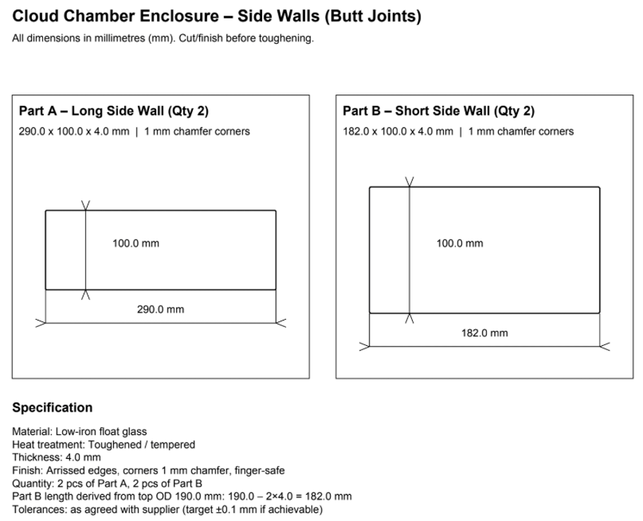
One side needed a notch cut to allow silicone hoses to pass through for the IPA feed. This glass panel was sourced locally and was regular, untempered, float glass with lightly arched edges so it could be ground out.
There is a method to this madness: if the IPO vapour inside the chamber were to ignite, the overpressure would be more likely to cause this pane to shatter first, and because it will always be facing away from viewers, it reduces the risk of injury if that unlikely event were to ever happen.
Cutting a notch
The cheapest glass grinder from AliExpress was purchased to make the notch for the hoses. A good friend was kind enough to assist and was nearly blinded by the sun in the process. But it was all worth it.
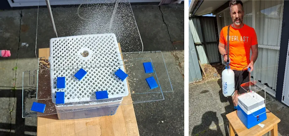
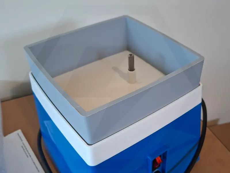
The strange thing about these glass grinders is that they all seem to ship with one large grinding bit that has an auger to lift water up to the working height, plus several smaller bits that have no auger and sit at completely the wrong height.
To make the grinder usable for this job, an additional riser piece was 3D printed to lift the work surface up to the correct height for the small grinding bit.
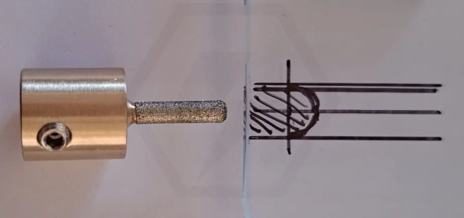
Because it’s hard to see in the picture, here is the diamond grinding tool used, with the area to be removed marked out.
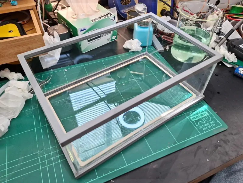
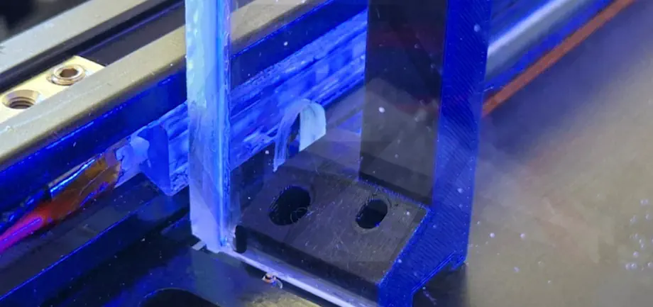
To aid in the final enclosure assembly, two 3D-printed frames were made to act as guides. A professional fish-tank maker would not need this, but we are not that. It also got a little messy with silicone being smeared about, resulting in many hours of vigourous razerblade activity after it had all set up.
ℹ️ Use a natural-cure silicone sealant and leave it for at least 48 hours. Acetoxy sealants release Acetic acid (vinegar-smelling) that can tarnish the silver frit
And finally, a close-up of the notch for the hose passthrough.
READER FEEDBACK
Join the discussion
Questions, build notes, corrections, and experimental observations are welcome.