FREQUENTLY USED TOGETHER
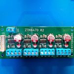
One board for a rig's auxiliary loads and fans: twelve PWM load channels, each with its own current monitor, plus six 4-wire fan controllers with tachometer feedback.
COMPATIBLE EXPERIMENTS
REGISTER INTEREST
We build these in small runs. Tell us you'd buy one and we'll email you when a run is confirmed. No payment, no commitment.
Sign in to your Zaptronics account to register interest. A free account takes a minute.
Lights, heaters, fans, the odd solenoid: every experiment has a pile of small loads that need switching. The ZTM-PWM handles them all from one ZapLink TWI port.
Twelve low-side PWM channels each switch up to 2 A, with 256-step duty control. Because the switching is on the low side, every load can run from its own supply, anything up to 54 V, or from the board's VIN, which is brought out on the load header for convenience. Each channel's current is measured across its own 50 mΩ sense resistor at the ground end, so a 54 V load is measured just as easily as a 5 V one.
Six 4-wire fan channels run open-loop on PWM or closed-loop to a target RPM, with tachometer readback and stall detection. Each fan's supply is jumpered to VIN or VIN_ALT, so 12 V and 24 V fans can share the board.
Power-up is designed so nothing twitches. A hardware supervisor holds the PWM chip in reset until the supplies are good, and the board signals POWER_SAFE on its ZapLink port when it's ready for the bus. Interrupts from all three chip types share one active-low IRQ line, so the host hears about a stalled fan without having to keep asking.
Switch them through a relay, with the ZTM-PWM channel driving the relay coil.
Inductive loads require suppression at the load. The on-board TVS provides transient protection only and is not intended as the primary repetitive flyback clamp.
Motors, solenoids, pumps, relay coils and anything else with a coil must have their own flyback diode (or other suppression) fitted at the load. That includes a relay used to switch a bigger load.
QUICK SPECIFICATIONS
SPECIFICATIONS
| Supply inputs | VIN and VIN_ALT |
| Load channels | 12 × low-side PWM, 0–100 % duty, 256 steps (Semtech SX1509) |
| Load switching | Low-side MOSFETs driven by Microchip MCP1415 1.5 A gate drivers |
| Load current | 2 A max per channel |
| Load voltage | Any external supply up to 54 V on the low side; VIN available on the load header |
| Current monitoring | 3 × Microchip PAC1954 (PAC1954T-E/4MX) four-channel monitors, 50 mΩ 1 W low-side sense resistors, 16-bit, on-chip energy accumulator |
| Fan channels | 6 × 4-wire PWM fans (2 × Microchip EMC2303), 26 kHz drive, 256 steps, tach input, closed-loop 500–16,000 RPM, stall detection |
| Fan supply | Jumper-selected per fan, VIN or VIN_ALT |
| Extra I/O | 4 GPIO (input with pull-up/down, output, or edge-triggered interrupt) |
| Board power | TI LM5168 buck regulator, switched by the module Enable |
| Interface | ZapLink TWI (I2C, 400 kHz) |
| ZapLink facilities | Enable, IRQ (active low), POWER_SAFE |
| Software | Open-source C11 driver available, with Pico SDK binding, portable to other MCUs with I2C |
FREQUENTLY USED TOGETHER