The Cirrus 1 cold plate is a hybrid cooling assembly that combines thermoelectric cooling with vapor-compression refrigeration. At its core is an array of eight thermoelectric cooling modules, or TECs, which pull heat out of the cold plate and dump it into a glycol-cooled aluminium block below.
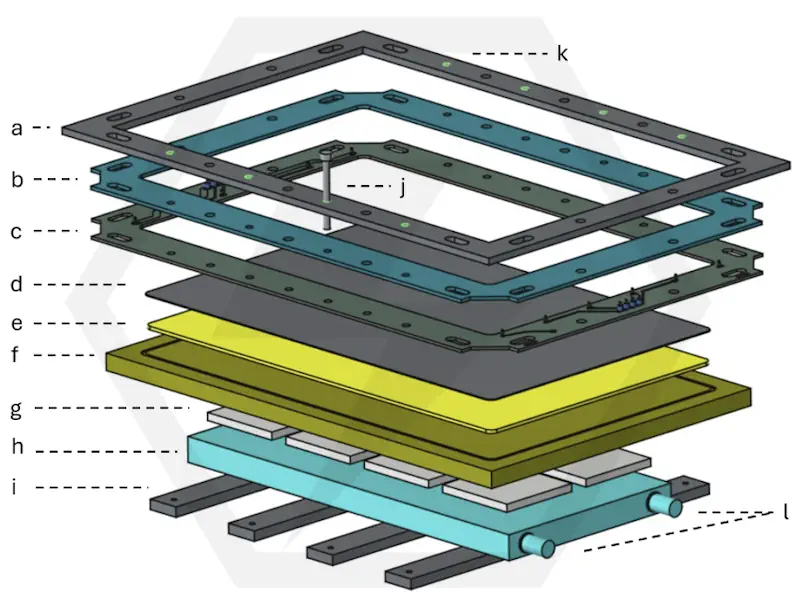
The entire cooling stack is held under compression by a 4 mm stainless-steel clamp ring (a) on top, eight M5 screws (j) at locations (k), and four 8 mm stainless-steel bars (i) below. Together, these parts clamp the assembly evenly and hold the TEC modules firmly against the copper cold plate and the aluminium cooling block.
Between the clamp ring and the cold plate are two FR4 PCBs, (b) and (c). These act as both a thermal break and an electrical passthrough to the removable glass chamber, which is not shown in this diagram.
The cold plate itself is a 10 mm copper plate (f). On top of this is a 1 mm black anodised aluminium finishing plate (d), which provides much better visual contrast for the vapour tracks than bare copper. The copper and aluminium plates are bonded together using Bergquist BOND-PLY (e).
Eight TEC1-12705 Peltier modules (g) sit below the copper plate and transfer heat into the aluminium cooling block (h). From there, the heat is carried away by circulating glycol-water that is held at approximately −20 °C.
PCB Break
The PCB Break, made from boards (b) and (c), is vertically symmetrical so that the two halves can meet each other and remain electrically compatible. Each half is made from single-sided PCB material, with the copper trace sides facing each other in the middle. This leaves the two outer faces as plain insulating FR4.
The Break has two primary functions. First, it acts as a thermal break between the copper cold plate below and the stainless-steel clamp ring above. Second, it provides an electrical pathway between the main enclosure and the edge of the removable glass chamber.
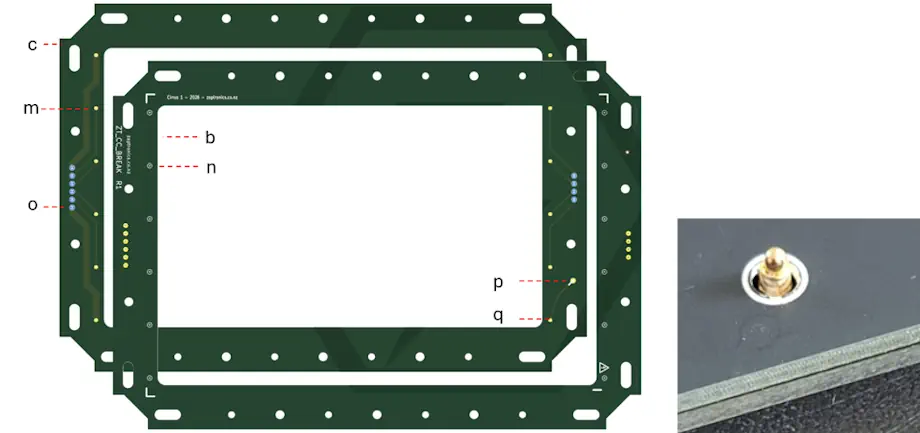
Pogo Pins are soldered to the pads (m) on board (c), while matching 2 mm holes (n) are drilled into board (b). When the two boards are brought together, the pogo pins emerge through the holes, and the upper board acts as a standoff for the glass chamber.
Special consideration is given to the high-voltage feed (p) and its corresponding exit location (q). This keeps the ion-sweeping connection physically separated and routed in a more controlled way.
BOND-PLY Side Quest.
One of the first parts I fabricated for this project was the copper cold plate. The perimeter channel acts as a gutter, allowing liquid IPA to drain away from the active surface. From the factory, the surface finish was highly polished, but the more I handled it, the worse it became. Once I removed the protective oil, the copper started to tarnish in an unpleasant, patchy way. Naturally, I also managed to scratch it.
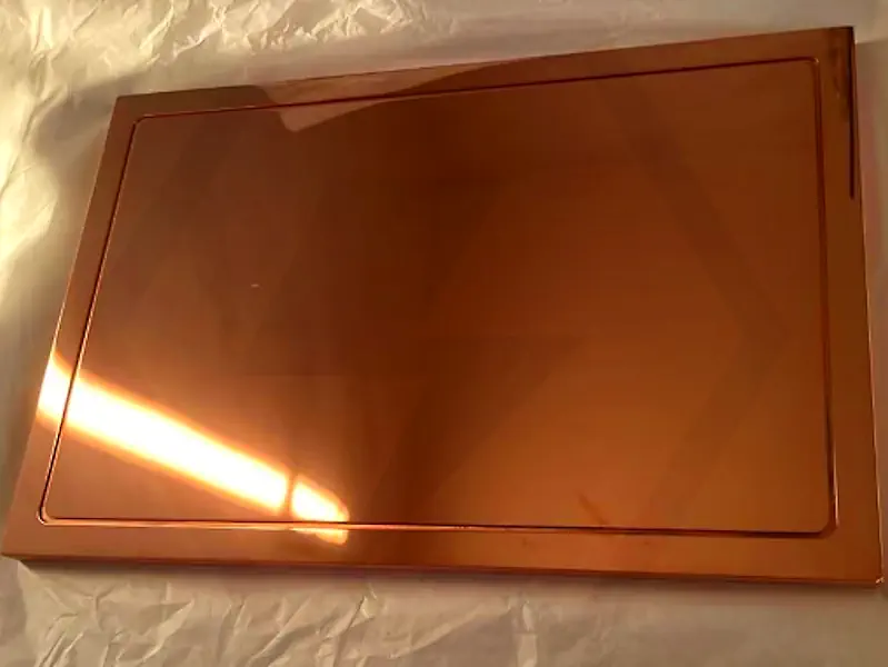
It quickly became clear that keeping the bare copper looking good was going to require a lot of maintenance. It also had not occurred to me at the start that a reflective surface would make photography difficult and reduce track contrast. So I decided to cover the copper with a 1 mm black anodised aluminium plate.
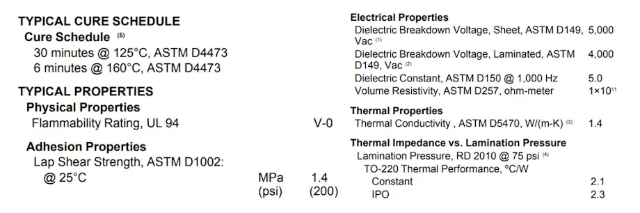
To get the best practical mechanical and thermal bond, I used Bergquist BOND-PLY LMS-HD, a thermally conductive silicone laminate. The particular sheet I used was 0.25 to 0.46 mm thick and has a thermal conductivity of 1.4 W/(m·K). That is not especially high compared with top-end thermal pastes, but in this case I needed the two plates to stay permanently bonded together. There is no useful clamping force that can be applied to this interface after assembly.
The datasheet says the material can be baked for 30 minutes at 125 °C. Ideally, according to note 4, this would be done while applying 75 psi to achieve the lowest thermal impedance. Since I do not own a hot press, I decided to improvise with a vacuum bag and a kitchen oven.
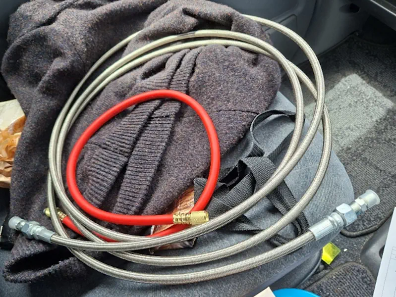
This led me to purchase the most expensive hose I have ever bought, so I can safely say that achievement has now been unlocked. It is 4 metres of PTFE hose with a stainless-steel outer braid. One of the Pirtek employees crimped the ¼” BSPT fittings onto the ends.
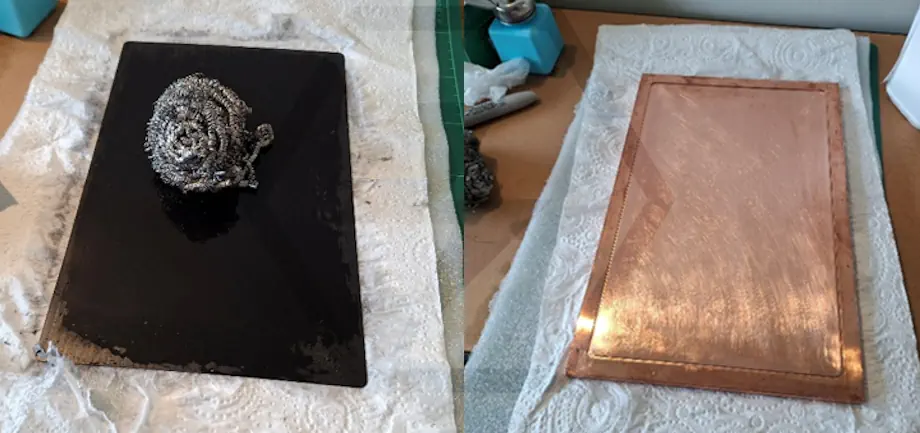
First, both surfaces were scuffed to improve adhesion. There goes that lustrous copper finish.
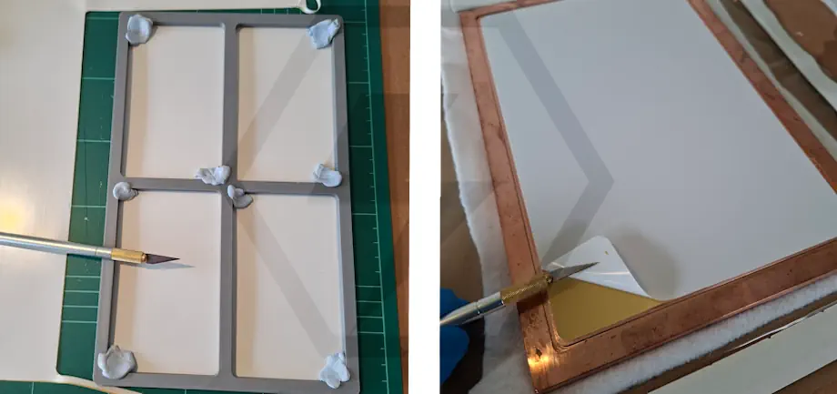
The BOND-PLY was cut using a 3D-printed template and then laid down onto the copper plate. The surface is tacky, so some care is needed to position it cleanly and work out any trapped air bubbles.
The black aluminium plate was then placed on top and rolled again to remove any remaining air bubbles. The whole assembly was loaded into a vacuum bag. The bagging materials came from New Zealand Fibreglass and were all rated to at least 150 °C.
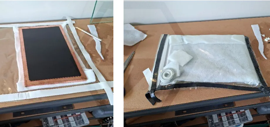
A cheap rotary vacuum pump was used to pull a rough vacuum while the assembly was inside the oven. The temperature was allowed to rise slowly.
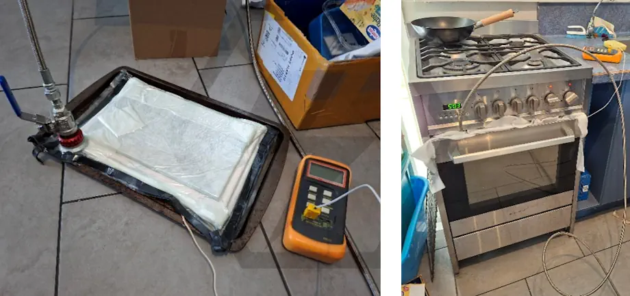
Unfortunately, I got a little impatient and raised the temperature above 125 °C. My temperature probe was measuring the copper plate, not the surrounding oven environment, and I ended up exceeding the limit of the bagging materials.
It was interesting to see how quickly the exposed copper oxidised after being baked.
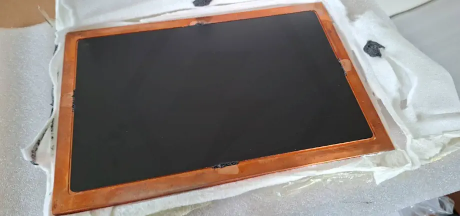
But it did actually stick. In hindsight, I may not have needed to go through quite such an elaborate process, as pressure and heat can also be applied as separate steps.
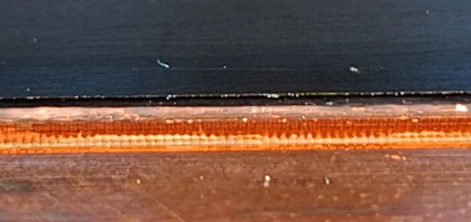
After the two plates were bonded together, silicone was maniacally injected around the interface edge to protect the BOND-PLY and reduce the risk of delamination.
Assembly
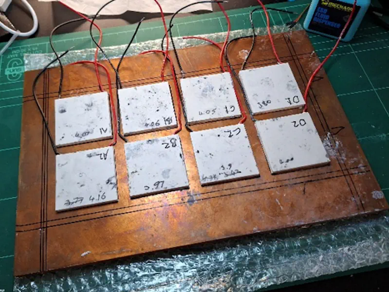
With the copper plate flipped upside down, the eight TEC modules were positioned using the layout guidelines. I used Thermal Grizzly Kryonaut Extreme KE thermal paste and went through 37 grams in total, including a few earlier experiments.
Eight PT1000 RTDs were prepared and epoxied directly to the copper plate. These were made by stripping 0.5 m of Cat6 cable and retrieving the shielded twisted pairs. After the RTDs were soldered in place, Kapton tape was used to insulate the pins, and heat shrink was placed over the top.
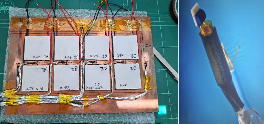
All of the RTDs achieved a good surface bond except for L2, which resisted being oppressed. L2 has about a 1 mm epoxy gap beneath it, but this should calibrate away.
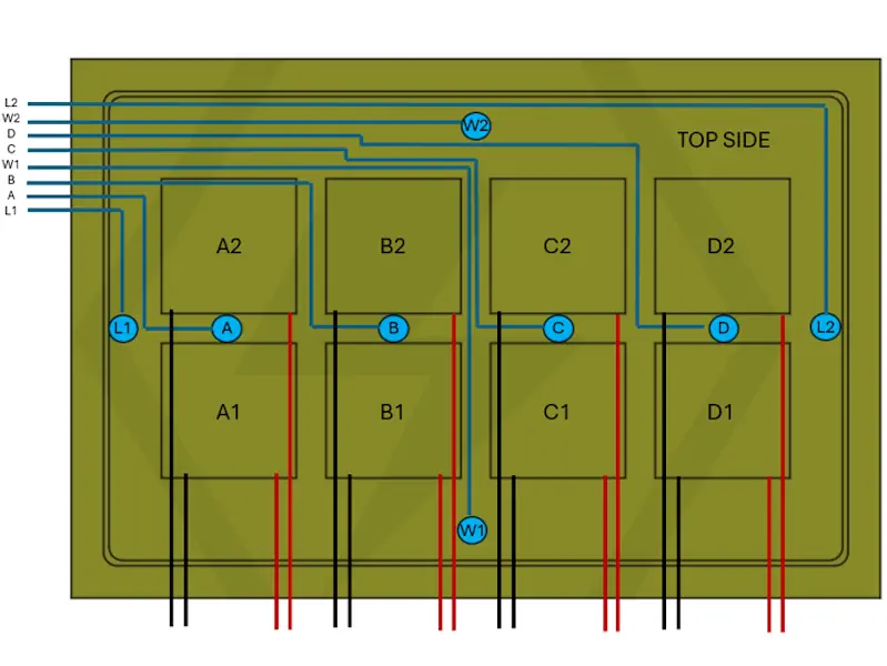
The diagram below shows the cable ordering when looking from the top of the cold plate. The RTDs are shown as blue circles, and the TECs are shown as black squares in rows 1 and 2. In a later post I’ll describe the TEC driver, and RTD ADC modules that were designed to make all of this work.
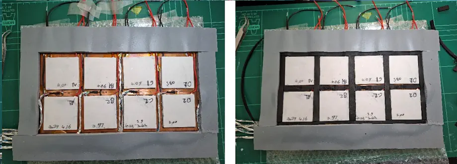
Two types of closed-cell insulation were used: 4 × 50 mm K-Flex foam tape, shown in black, and 6.3 mm Rogers BISCO HT-800 silicone foam, shown in grey. Both materials have self-adhesive backing and are easy to cut to size.
First, a boundary of HT-800 was formed around the area where the cooling block would sit. The gaps around the TEC modules were then loosely filled with K-Flex. A craft knife was used to shave the K-Flex down so that it did not protrude above the TECs, as this would affect the evenness of the clamping force.
Thermal paste was then haphazardly applied to the warm side, and the cooling block was put to bed.
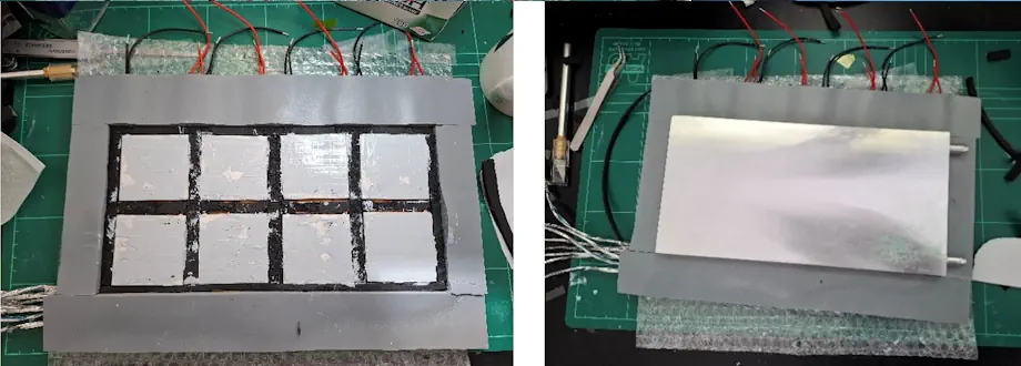
A 3.2 mm piece of blank FR4 was used as a thermal break, and the bolt ends were treated to a generous helping of CRC copper anti-seize lube to protect the stainless-steel threads.
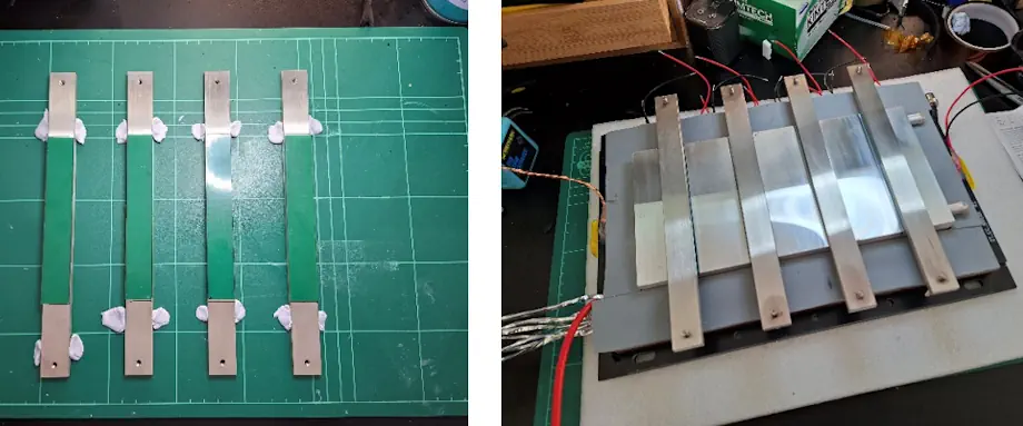
More insulation was applied to fill every last exposed area.
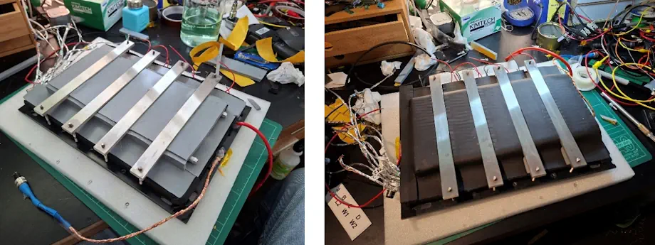
The earth bond for the copper plate was made using a tapped M4 hole, which I will bolt a lug to later. If only I had remembered to do this before assembling the entire thing.
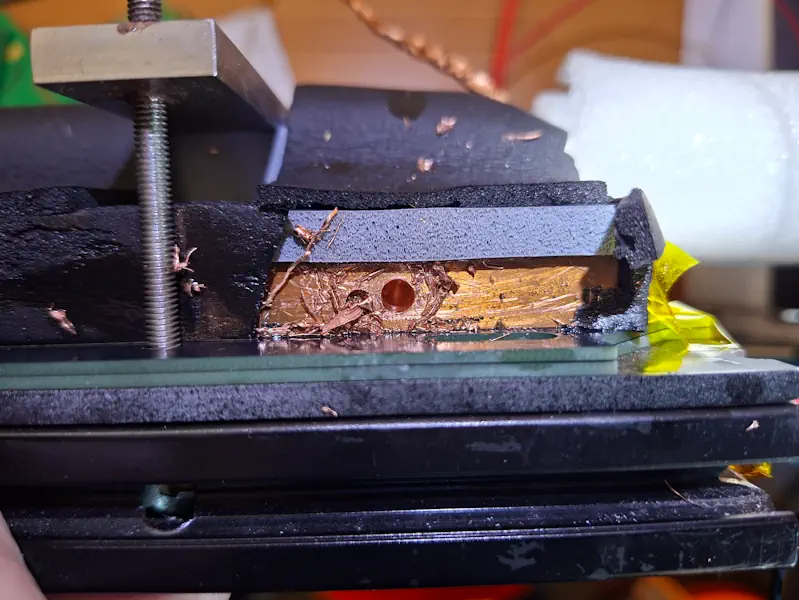
I am pretty pleased with the end result. Hopefully, it is now much clearer what we are going for. The glass enclosure will sit on top of the pogo pins, creating the electrical contacts for the top heater, ion-sweeping electrode, and spare connections for any future sensors inside the chamber.
Off to the right is the digital torque wrench that was used to ensure even tension across all of the bolts.
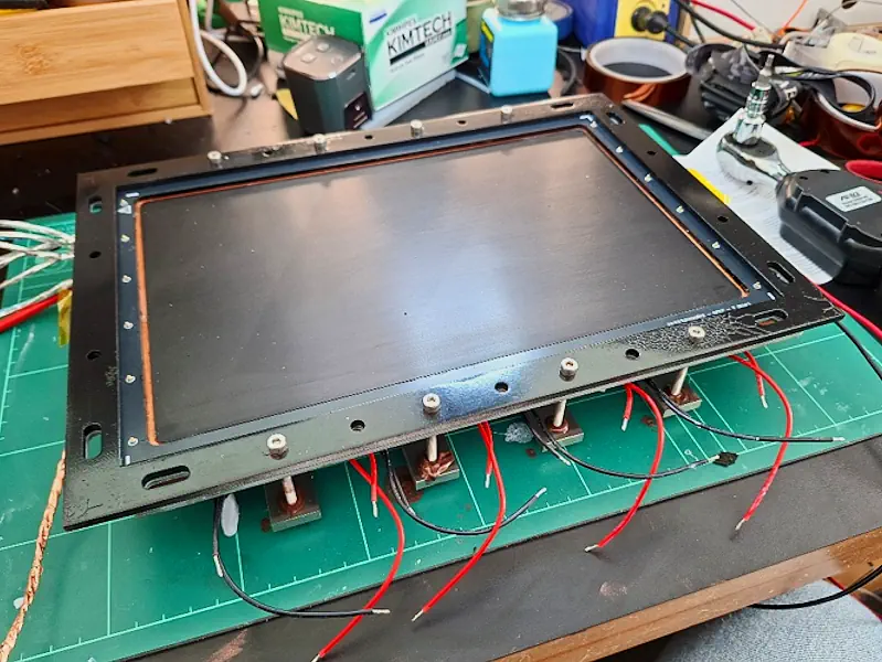
The exposed copper ring is a CNC-machined gutter that allows liquid IPA to run off into a collection channel. From there, it will eventually be pumped away, filtered, and recycled back to the top of the chamber.
But that’s a story for next time.
READER FEEDBACK
Join the discussion
Questions, build notes, corrections, and experimental observations are welcome.